Copyright (c) 2001 Template Graphics Software, Inc.
Written by Philip Staiger
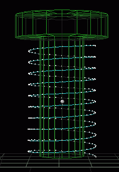
One of the rather interesting things to model is a screw, and in particular the thread spiraling up along the screw. Also, do you want a single slot or Philips-style head? Is the tip of the screw flat or does it become pointy? etc etc.. In this tutorial, we'll explore some tools Amapi offers to help you model this or that.
The Main Cylinder
Assuming you're a little bit familiar already with the basics of the Amapi user interface, let's just say we'll use the Basic Wireframe mode and the workshop interface, also known as the Natural Design Interface. Let's jump right in and go to the Construction Toolkit. Select the 2D Draw tool, which displays various curves such as Circle, Arc, Polyline etc...

Use the numeric '5' key to select a view looking down from the top. Select the circle and click once somewhere in the middle of the screen to place its center, then move the cursor out a little bit to set the size (you can see the radius' value change in the lower left corner) and click again to freeze it the desired size. Then use the +/- keys to increase the number of points on the circle. In fact, let's use numeric input here, so hit the TAB key and enter 20, then hit Enter again to finish. We now have created a circle with 20 points along its perimeter.

Now switch back to a front view (using the "2" key) and position your camera so that the circle is close to the bottom of the view. You can use some of the viewing controls in the middle of the control panel at the bottom of the screen for that, or if you like the Arrow keys for rotation, use them with the CONTROL key pressed down and they'll switch from rotating (orbiting the camera) to translating (moving) it. Zoom out so you have plenty of room for an extrusion in the upward direction.

Click the Extrusion tool  and click the circle.You'll see two axes (red + green, i.e. 'X' and 'Y')
and a rubberband circle connecting to the base circle, with 20 rubberband
lines betwen the base and the active circle following your cursor. (this
is a mode of the extrusion tool where you manually create the extrusion
with just the section. Another mode could use is to create the extrusion
path (lathing profile) as a curve, and click that instead).
|
Since we only want to go along one axis, namely the vertical axis, hit the SPACEBAR to toggle between the two or a single axis, until you see just one vertical (green) axis and you notice that the rubberband objects and the circule and cursor only move up and down. Move the cursor towards close the top, and click to set the second section. If you know exactly how much length you need for that screw, you can again use the numeric input option in the lower left corner - just hit TAB to enter the value(s). Then hit the SPACEBAR again until the horizontal-only axis shows in
Red, allowing you to go just sideways. We're now going to make the head
of the screw, and more precisely, the bottom flat portion of it.
|
 |
| You can now move the cursor sideways in order to set the size of the head which will be built here at the top of the screw. |  |
| Click and start moving up for the screw head's
side walls. Again, use the SPACEBAR to force it back into a vertical-only
axis.
Move up a bit until you have the amount you want for the head's extrusion depth. |
 |
| Then start moving to the enter of the top part of the head. Note that you don't have to go exactly and totally to the center, because after the next click and when hitting Enter, the Extrusion tool will show you the two openings. |  |
|
|
 |
|
Amapi automatically finishes and exits the Extrusion tool when it finds that there are no more openings (as soon as we clicked the last opening). Hit ENTER for a quick test rendering. Use the arrow keys to orbit your camera up and look at the top to make sure there's no more opening. Use the View>NewView>FreeView
|
 |
So far so good. Now let's make a thread.
The Thread
I'm no expert at the physics and mathematics of threads on screws, so I'll be happy with something that just visually is acceptable. Here's my idea of making a thread:

A circle appears to follow the cursor, place it at the bottom of the
screw.

Click, then set the radius of the helicoidal circle.

Make sure the radius is big enough so that it extends well beyond the
cylinder of the screw.
This circle will control the outer limit of the thread.
|
|
 |
Now let's use a little bit of Math. The numeric input shows a number of Slides parameter, as well as the Height. If you move it to the top of the screw (bottom side of the head), you can see how much the total height is that's available for the thread. The information shown here is for a single helicoidal sweep. Thus, if you want ten threads total, you'll have to divide that distance by 10.
You can also temporarily enter the measurement tool (lower right
of the control panel, or from the Tools menu) and check the dimensions:

In my example, there's a bit more than 26 cm (that's a long screw !).
I'll want to give it a little bit of margin. Therefore I'll divide
25 cm by 10 and enter the numeric values for height as 2.5, and 10
for the number of slices.

You can then change the number of points. Hit Enter to accept and finish.
Or, if you want to change the radius at the top of the helicoidal from
the value at the bottom of the helicoidal, use Backspace, Amapi will let
you reposition the top with the number of slices (10) unchanged. Then hit
Enter to finish.
This helicoidal curve is going to be the sweep path of a triangular section.
Let's make that section now. Select the Orthographic view mode for a
clear view and zoom into the lower right area of the thread, so you can
use the curve's profile as a reference for a triangular profile.

In this example it's a simple triangle (make sure it's closed). You
can of course be much more inventive, with some rounded bevels on the tip
of the thread. You will want to make sur that the right-side tip of the
triangle reaches and snaps to the outer-most point on the helicoidal curve.
Also, have a little bit of overlap on the left side of the triangle, with
the cylinder wall.
Go back to perspective view. Make sure the triangle is planar, inspect it from different angles. Use the Stretch tool, Scale tool or others to fix it if it's not the desired triangle. Use the Snap tool to snap the right-side vertex of the triangle onto a vertex at right on the thread's sweep curve.
 |
In fact, if you decide to draw the triangular section separately on the side, or import it from a other file like Illustrator or DXF or PICT vector file, you might be looking at something like this, where the section is not connected to the sweep path. |
But that's no problem, as you can use the Snap tool  from
the assembly toolkit to snap the triangle to the desired point on the sweep
curve. Make sure, before you click the snap tool, that the section triangle
is the current object. Then click the Snap tool, then click the desired
vertex on the triangle. In this example, click the righ-side point (at
3 o'clock).

Then, click a point on the sweep curve. Here we just clicked the point
at the start of the sweep curve to the bottom right of the screw. If necessary,
use the Scale tool to make the triangle a little bit larger so it slightly
overlaps and cuts into the screw's cylinder wall. This is so that the boolean
operation following later on will indeed find an intersecting part between
the two objects. When scaling the triangle, select the right-side point
as the scale reference point (use Option click on Mac, Right-click on PC).

Ready for the Sweep Tool
Make sure the triangular section is the currently selected object. Click the Sweep tool, then the helicoidal curve to sweep the curve along the helicoidal path.
There are several ways that the sweep can come out, but the first one should work just fine in this case. If your scenario is a bit different, you may have to get different orientations for the section along the sweep path, or use the SPACEBAR to toggle the section's orientation as it progresses along the sweep path, and you can also change the sweep size with +/- keys in some of these cases. Some of these will cause the section to go perpendicular to the curve, or parallel to it, or tangential, or keep its default orientation, etc...

Youll also see the two openings at either end of the swepth 'tunnel'. Click the top and bottom openings to close the sweep surface into a solid volume. Use the Arrow keys or the Trackball in the control panel to inspect the result from different angles. Do some test renderings with the ENTER key.


As you can see here, we did a slightly sloppy work, because the sweep extends beyond the bottom end of the screw's cylinder. But that's no problem, as we can easily scale the thread along the vertical axis.
Click the thread to make it the current object. Use the Scale
tool from the Assembly toolkit.
This is a proportional scale going in all 3 main axes by default, but
we'll easily switch to a single axis with the SPACEBAR. But first, notice
that the scale reference point, marked with an 'X', is at the bottom of
the thread. 
We need to reposition it towards the top end. On PC, click the right
mouse button. On Mac, do an Option-Click. Or, select the 'X' icon in the
assistant palette (next to the lasso and bull's eye cursor icons) at the
top if you have it enabled.
Click somewhere at the top end of the thread to place the scale reference
point there. Next hit the SPACEBAR once or twice to get the proper axis.
Select the vertical-only (green) axis).  Then you're ready to click and grab the bottom end of the thread's bounding
box and change its scale so that it barely comes down to the bottom end
of the screw's cylinder.
 You may
want to make sure in fact that it's a little bit shorter.
Ready for Boolean Punch
We now have two solids (known as volumes to Amapi): the simple screw
plain cylinder with head, and the thread. We'll want to perform a boolean
operation that combines the two and doesn't leave anything inside that's
overlapping. Select the thread. Then select the Punch tool from the modeling
toolkit ![]()
Click the other object (the plain screw with head) and wait a short while. Ok, wait a long while if you're on a 166 MMX with just 64 MB RAM, but if you are on a modern-day system with 500+ MHz clock speed and 128 MB or more of RAM, you should not run out of memory or go virtual, and in a short while, Amapi will display the first of a series of results. You can cycle through them all with the +/- keys. The first one I got looked like this: (click the image at left for a larger view)
This one is not the right candidate, it shows what's left of the screw after the thread has eroded (cut out) off the part where the thread overlapped into the screw's cylinder.
Evidently that's not what we're looking for. Amapi took the first object (the thread) and used it to cut out that shape from the second, the screw. Interresting, but not the thing we want. So, hit the "+" key on the numeric keypad to advance to the next candidate.Here it is:
Now this looks more like it. We can zoom in to see details and recognize indeed that this one represents the combination of the two parts with no inner parts left due to overlapping details.
Hit Enter to accept this one. Or, if you're curious, use the +/- keys a few more tiles to cycle through more results. You can find separation surfaces between the two parts, or what's common to both, or even the intersection curves.

Finishing the head, we can make a cut out with a narrow rectangular block. Create a cube, and use the Scale tool to shape it. While in the Scale tool, hit SPACEBAR to toggle from both to just one axis. This lets you squeeze the cube into an oblong block.


And of course, we'll now use the Boolean (Punch) tool, to cut the groove into the top of the screw's head.

Tweaking and Adjusting the shape
Ok, so now we have the basics done, and we can do some adjustments to
the shape. For instance, we may want to shrink the tip at the bottom of
the screw, to make it pointy, and thus turn this into a metal screw. Or,
we may want to elongate the part which has no thread at the top end of
the screw, between the thread and the bottom of the head.
|
One tool that's very useful for this is the Meta-NURBS tool, first icon in the modeling toolkit. 
Amapi creates a sort of scaffelding, a framework, on which you can select
control points. The geometry in the immediate nearby area of that controlpoint(s)
gets affected by what you do to the control point, such as move (drag)
or scale it.
|
 |
You can also use the +/- keys there to increase the density of the control framework, and get a more localized effects of the control points.
Then, you can use the 'Lasso' cursor (Option-click on Mac, Right-click
on PC) to select a subset of the points. For example, select all control
points at the bottom of the structure:


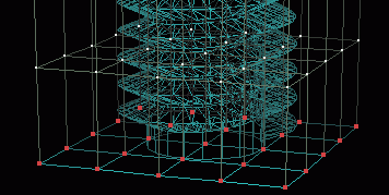
| Hit ENTER, and you'll see the selected points in red. You can now do various things to just that subset of control points. For instance, drag the points way down and to the right, to stretch that section. |  |
Perhaps a more useful thing is the Taper tool, which works on the entire
object (not on a subset of the framework or scaffelding). 
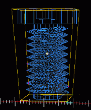
A global control box appears in yellow. Click the bottom base and move
the mouse to make it smaller. You can also hit the SPACEBAR if you want
to toggle the active faces of the control points to the other, perpendicular
axis layout.
 |
 |
 |
 |
Opps, that last one went a little bit too far :-)
Let's make sure we don't overshoot this tapering thing...
Here's the rendering on a useful result. 
And here are a few other things you can easily do.
Using the Bend tool in the MetaNURBS group
Here we selected the points of the head (without the thread) and then used the Stretch tool to move that part away from the threaded part of the screw, essentially elongating the neck.
Using the MetaNURBS tool to squeeze in the middle, and Bend tool.
Well, there's many more types of screws, and many more different approaches to making them. I guess this is Chicken Soup for robots...Enjoy!
